MuJoCo for FEA
2025-03-17
This guide will describe the way in which MuJoCo, a dynamic rigid body simulator, can be used in the workflow of mechanical analysis. Fine details in the simulation setup and MJCF (XML used by MuJoCo to describe the robot) have a significant impact on what MuJoCo gives you. In this guide I will walk through the deep dive I took across the docs, experimentation, and understanding how MuJoCo works. This ensures your simulation is set up as expected.
Minimal MuJoCo setup
import mujoco
import mujoco.viewer
import time


model = mujoco.MjModel.from_xml_path("dynamic_body_sim/utils/xml_create/kbotv2p0/scene.xml")
data = mujoco.MjData(model)

mujoco.mj_resetData(model, data)

model.opt.timestep = 0.001  # 0.001 = 1000hz

# Disable gravity
# model.opt.gravity[2] = 0


with mujoco.viewer.launch_passive(model, data) as viewer:

    target_time = time.time()
    sim_time = 0.0

    while viewer.is_running():

        # Step simulation
        mujoco.mj_step(model, data)
        sim_time += model.opt.timestep
        viewer.sync()

        target_time += model.opt.timestep
        current_time = time.time()
        if target_time - current_time > 0:
            time.sleep(target_time - current_time)
Getting started with MuJoCo is relatively easy. Above is a basic script to get you started.
Note that on mac you will need to run it with mjpython filename.py. The other important
part is to get an accurate MJCF - I will focus on the parts that relate to attaining forces in this
write-up, but don't forget other important factors, like accurately modeling your servos (getting armature and friction right).
Check through your MJCFs yourself but start with this or this converter tool
and then reference the official XML reference docs to edit the MJCF as
your use case requires.
Ways to Measure Forces
The most obvious way to measure force is adding a force sensor at a site like
<sensor>
    <!-- Force sensor at the specified site -->
    <force name="force_sensor" site="force_site"/>
</sensor>
This measures the interaction force between a child and a parent body, the site the sensor attaches to should be the child body. The force vector it reads points from the child to the parent. There is a frequent pattern used in dynamic body simulation software of creating a dummy body: see this discussion here
When using a force sensor, the forces are measured in the site frame.
You can also measure the force on a body directly
data.body("toplink").cfrc_int.tolist()

data.body("toplink").cfrc_ext.tolist()
cfrc_int measures the forces inside the kinematic tree, that is the interaction force with parent body. The cfrc_ext measures the external force acting on the body. They are both 6 dimensional (per joint), arranged in [rotation(3), translation(3)]
The internal force is measured in the child's link frame.
A force sensor must be defined in the XML (regardless of site location) in order to query force values.
Above is a comparison between expected internal and external forces and what it was measured as using the cfrc.int and cfrc.ext. Both of them match.
More types of forces
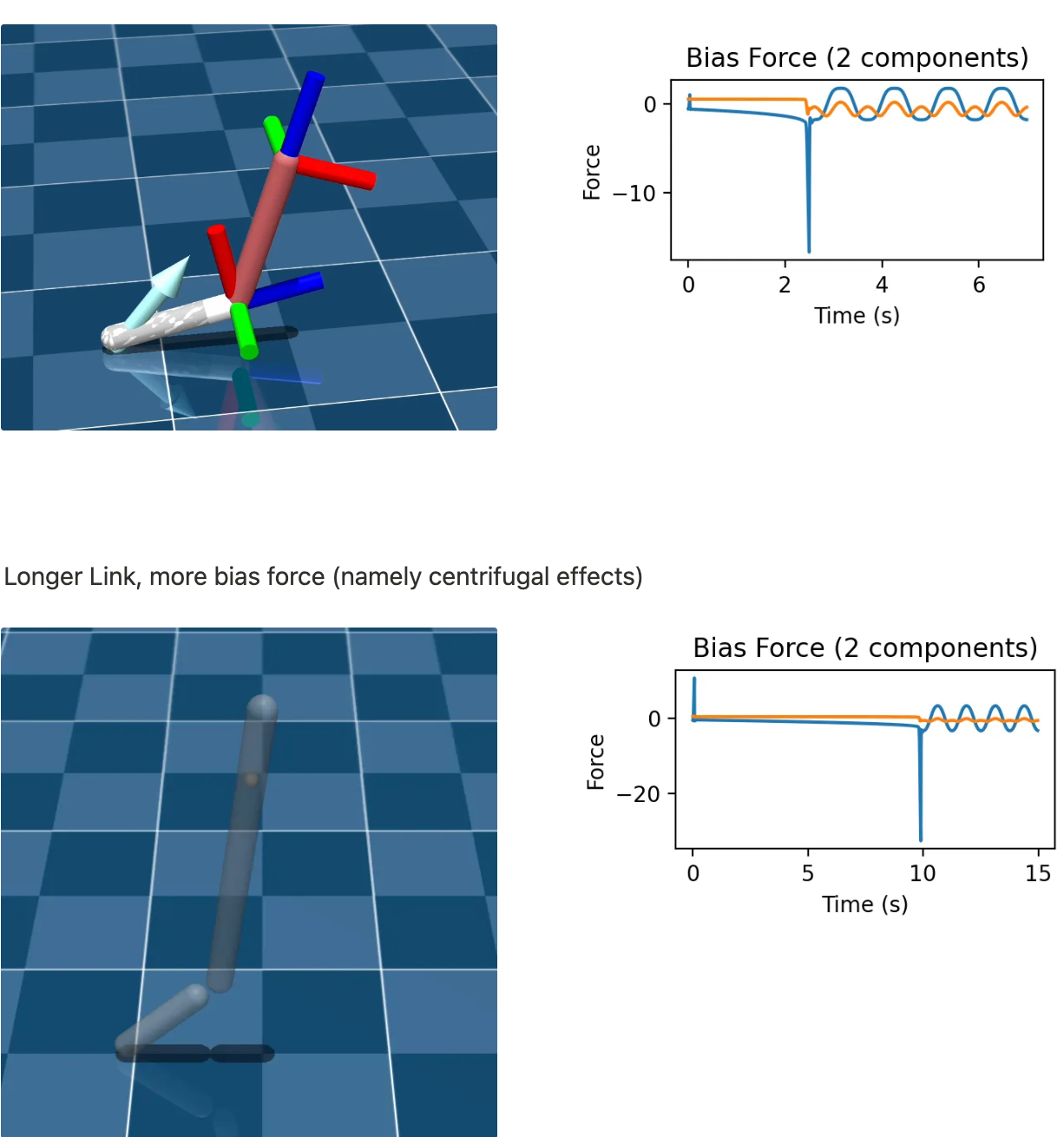
M(q) is mass matrix. C(q,v) is bias forces, g(q) is gravity. q is joint angle in generalized coordinates and is joint acceleration so forth. is joint torques
Bias force includes coriolis, centrifugal and gravitational. In rigid-body dynamics bias force/nonlinear force are all the velocity-dependent and config dependent forces in motion. It is often used in robotics to account for these extra forces. Intuitively, if you cancel out all bias forces, it would be like if robot was in free space.
Experimentation
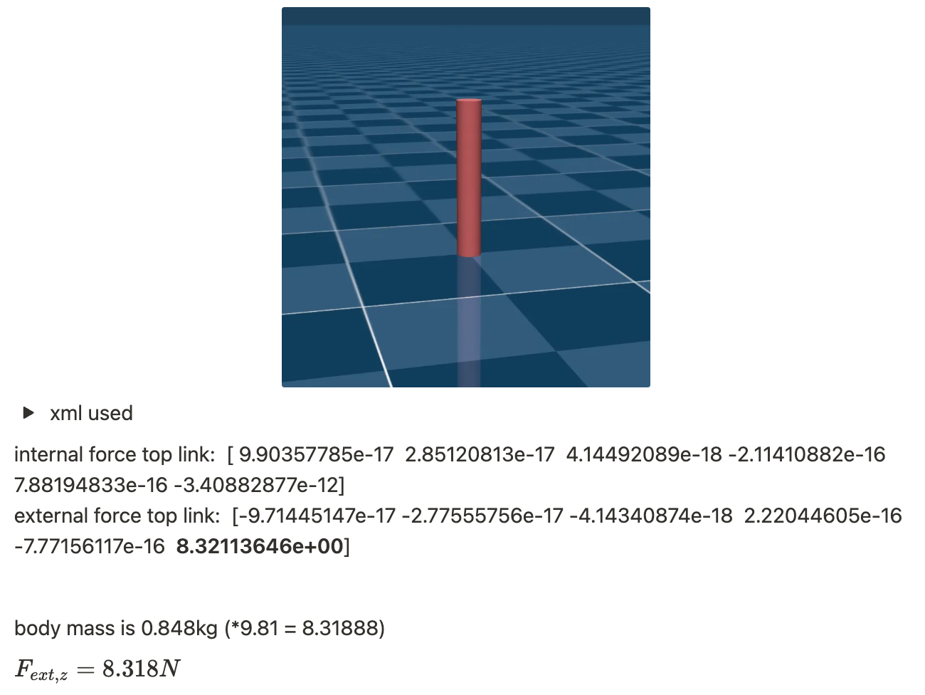
External force correctly measures normal force
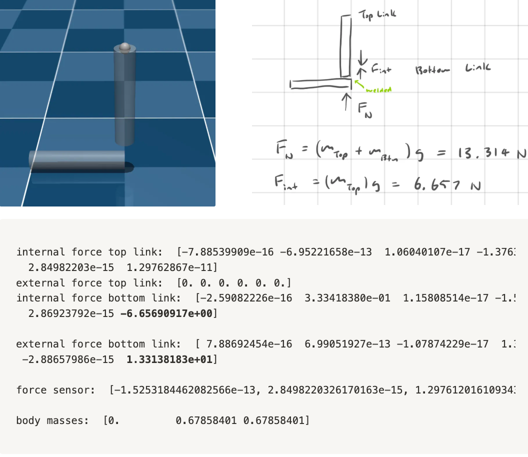
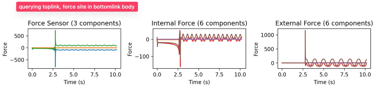
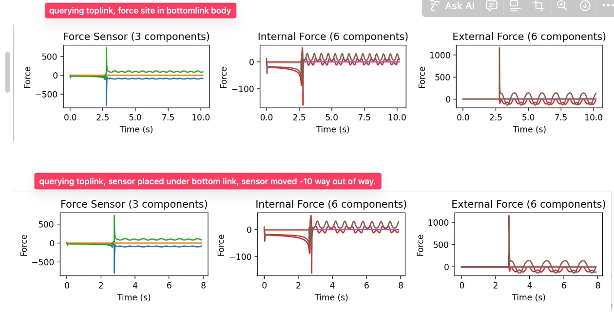
Force sensor vs internal force
In this example a suspended two bar linkage has a joint actuated, and it pushes up on the bottom link until when the bottom link is colinear (the inputted target position).
Force sensor != internal or external forces, each measures something different (see above)
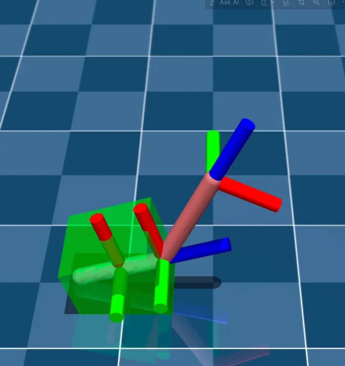
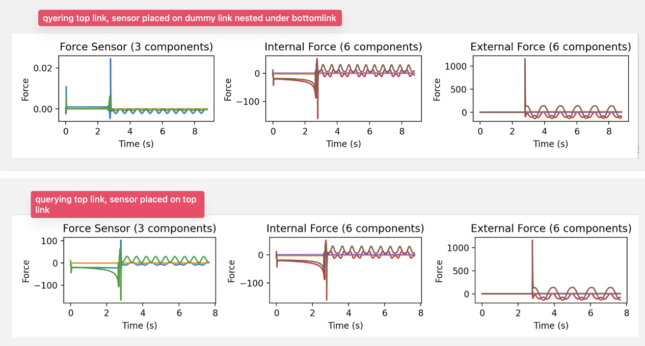
Sensor site placement does not matter
Sanity-check bias force in MuJoCo (longer link should have larger centrifugal effect)
For querying body internal or external forces, the sensor placement does not matter
Attaining Force Values to use in FEA
With a basic understanding of how forces are defined and measured in MuJoCo, I will now give an example of a real use case.
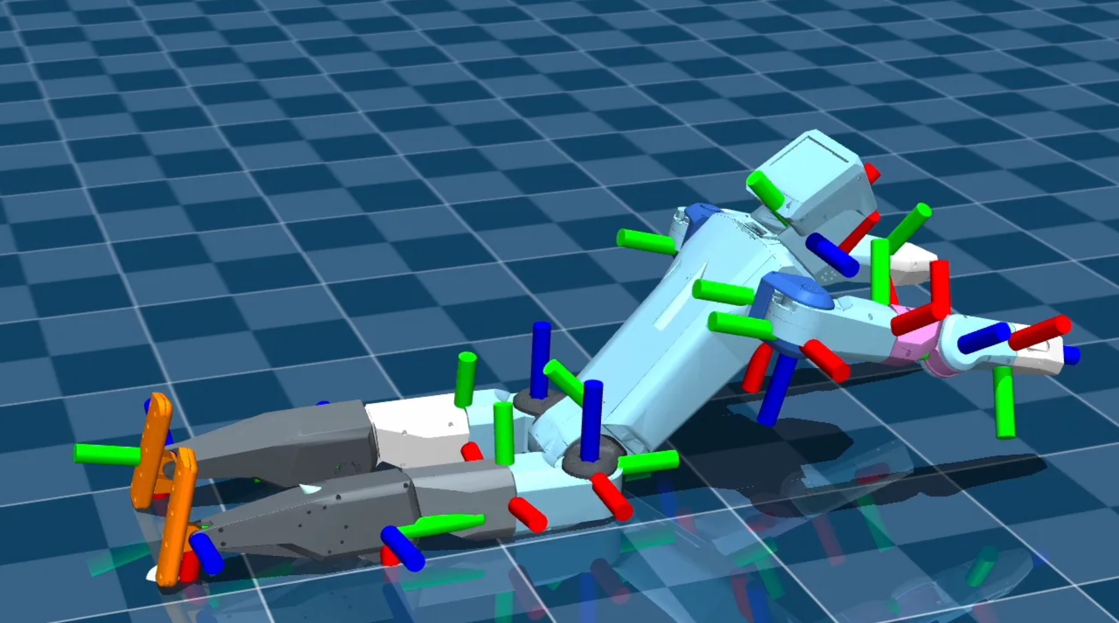
The motion captured is a K-Scale humanoid robot falling and landing. For example, if we are evaluating the strength or optimizing the weight of an idle piece on the legs, we would use simulation to estimate its structural integrity during specific motions before going to testing. Here are the data plotted during that motion. You can see how the force tracks with the fall (tracked in base position).
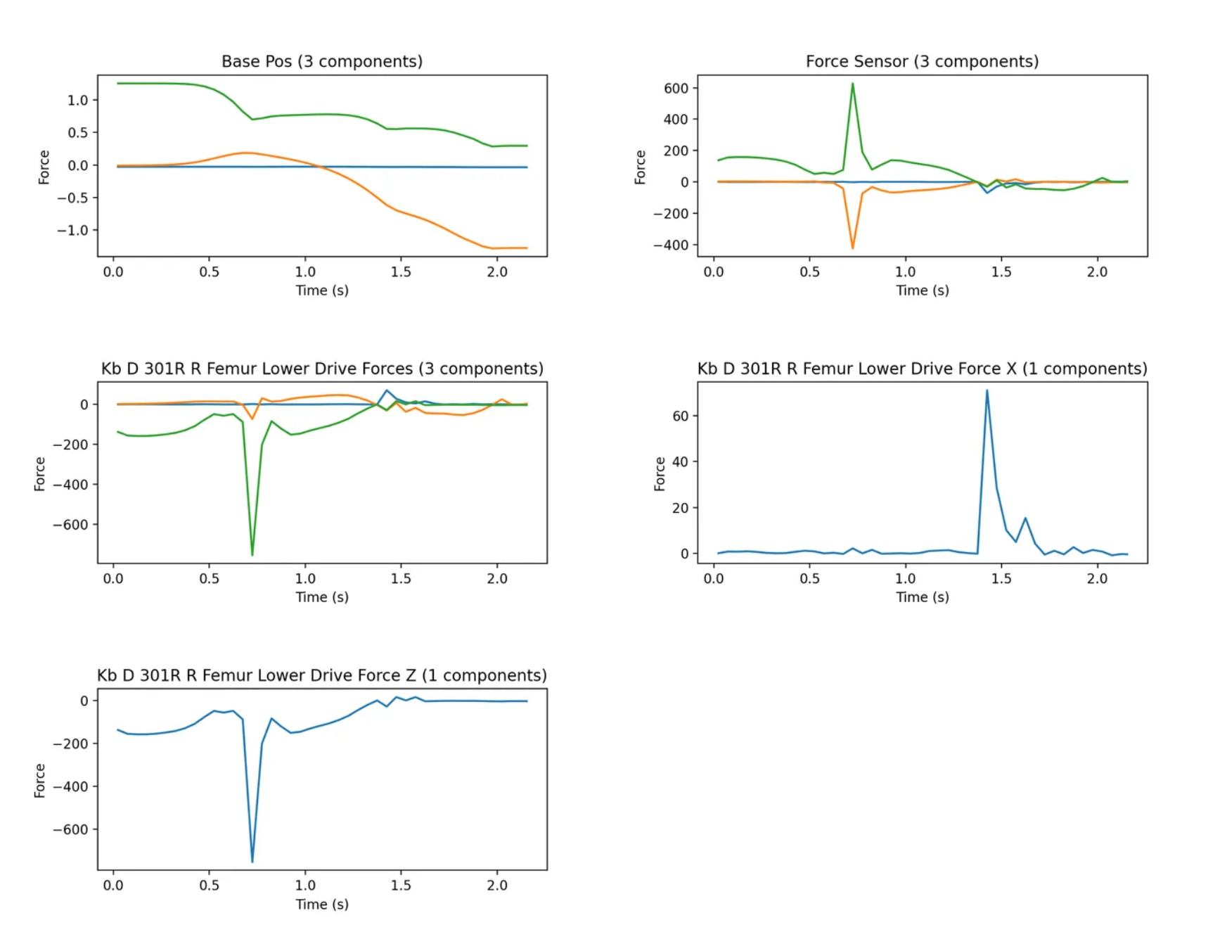
The force site is added in between the calf and the lower thigh. This will measure how much of the force is distributed from the floor, through the lower calf, and up to the idle side, during the motion.
<body name="KB_D_301R_R_Femur_Lower_Drive" pos="0 -0.142750 -0.029800" quat="0.7071068967259818 0.7071066656470943 0.0 0.0">
    <joint name="right_hip_yaw_03" type="hinge" class="motor_03" range="-1.570796 1.570796" axis="0 0 -1" />
    <inertial pos="0.000139 -0.010511 0.162474" mass="2.556834" diaginertia="0.018026 0.016368 0.004729" />
    <geom rgba="1 1 1 1" name="KB_D_301R_R_Femur_Lower_Drive_visual" material="KB_D_301R_R_Femur_Lower_Drive_material" type="mesh" mesh="KB_D_301R_R_Femur_Lower_Drive.stl" class="visual" />

    <site name="force_site" pos="0.0 0.0 0.0" size="0.01"/>

    <body name="KB_D_401R_R_Shin_Drive" pos="0.020600 -0.021000 0.212000" quat="0.5000001633974483 0.4999999999999733 -0.49999983660255165 -0.4999999999999733">
        <joint name="right_knee_04" type="hinge" class="motor_04" range="-2.705260 0" axis="0 0 1" />
        <inertial pos="-0.026847 0.095560 0.020795" mass="2.016717" diaginertia="0.017602 0.003759 0.017275" />
These forces can then be used in load condition during FEA. Results from each step of the simulation should be validated with real-world experimentation and measurement where possible.
MuJoCo Quick Reference
Get the body id with
body_id = mujoco.mj_name2id(model, mujoco.mjtObj.mjOBJ_BODY, "body_name")
data.xpos[body_id]
MIT controller on joint
def compute_torque(desired_pos, cur_poss, cur_vels):
    cur_pos = cur_poss[0]
    cur_vel = cur_vels[0]

    desired_vel = 0.0

    kp = 200
    kd = 10

    return kp * (desired_pos - cur_pos) + kd * (desired_vel - cur_vel)
 while viewer.is_running():
      data.ctrl = compute_torque(3.14, data.joint("actjoint").qpos, data.joint("actjoint").qvel)
      # data.ctrl = 5
Adding key callbacks
def key_callback(key):
    if chr(key) == ' ':
        data.qpos = np.zeros(len(data.qpos))
        data.qvel = np.zeros(len(data.qvel))
    elif chr(key) == 'R':
        data.qpos[0] = 3
    elif chr(key) == 'Z':
        global applying_force
        applying_force = not applying_force
        print(f"Applying force: {applying_force}")
    elif chr(key) == 'T':
        if viewer.opt.frame == 7:
            viewer.opt.frame = 1
        else:
            viewer.opt.frame = 7
        viewer.sync()

with mujoco.viewer.launch_passive(model, data, key_callback=key_callback) as viewer:
    # ...