[Automated Robotic Linkage Mechanism, Team]
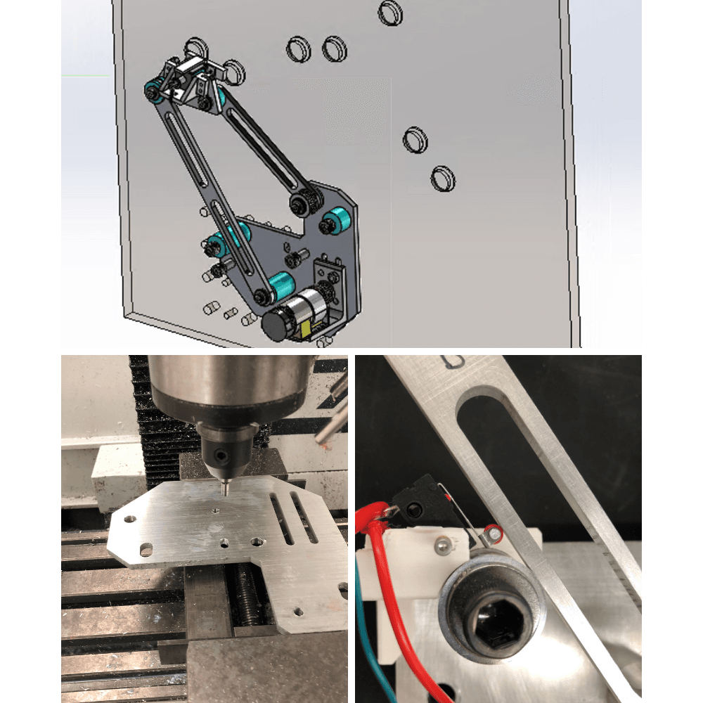
Goal of pressing three pairs of randomly-lit buttons as quickly as possible; done in a group of 4. The team worked together to wire and calibrate the PID controls. I was responsible for machining the ground plate, and one of the linkages, as well as designing the limit switch holder.
Final Video!
Final Video! The arduino controlling the linkage receives one of the three button codes, which is lit up, and controls the linkage to go there.
Challenge One: Kinematic Planning
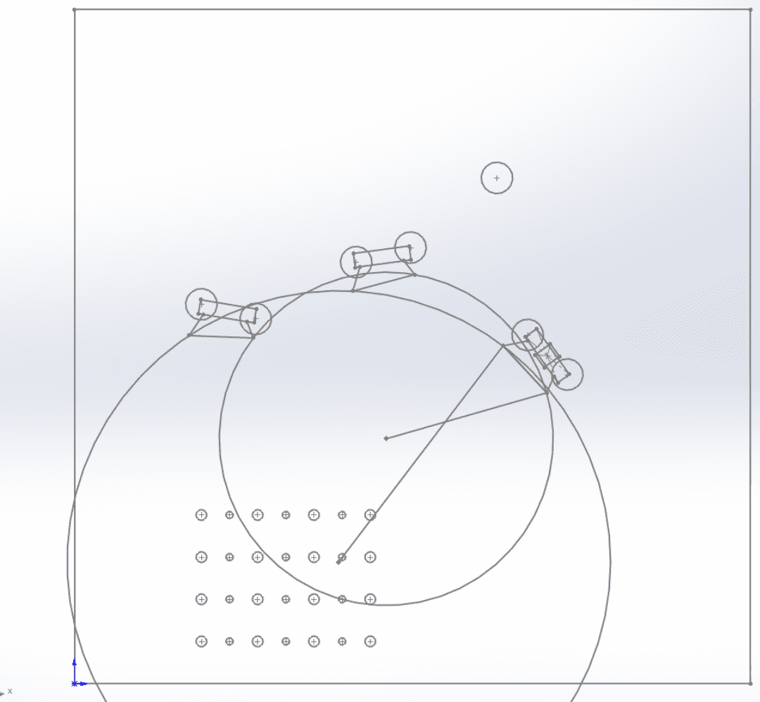
The graphical method of linkage synthesis was used to determine the stationary pivots. The transmission angle, which impact motor torques, was the main criteria used to select angle. The result of kinematic planning gives a mechanism that has a low moment of inertia and faster response time.
Challenge Two: Linkage Joint Hardware
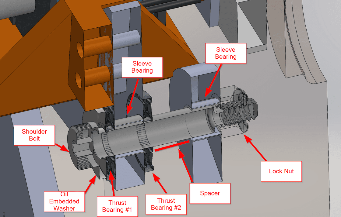
Linkage Joints need to be smooth rotating, sleeve bearing and trust bearings were selected. A minimal number of trust bearing is used in the design, as only one relative motion needs to be free-moving.
Challenge Three: Motor and Transmission Selection
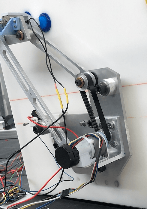
We evalauted options from spur gears, timing belts, chain belts: due to the limited space we choose timing belts. The transmission ratio was selected based on the inertia matching machine design principle.
Challenge Four: Electronics and Controls
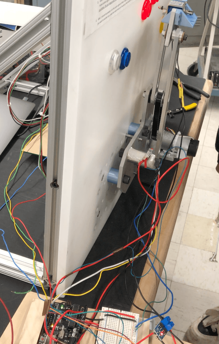
The Arduino-controlled system starts with finding the relative zero at the limit switch and then moves to the pre-optimized locations of the buttons using the relative encoder in the motor. PID parameters are tuned for best performance. The code was adapted from existing PID control code.